I have explored 3 basic suspension types for my tilting Free To Caster reverse trike. I will explain what I feel are the pros and cons of each with some illustrations of various concepts.
Scrub is when the contact patch moves sideways relative to the plane of the wheel. Scrub does not happen when the suspension travels inline with the lean angle.
Track is the distance between between left and right contact patch of the wheels. When suspension travel moves inline with the lean angle, at high lean angles track can be reduced. This has less negative effect than scrub.
Double A-arm
Short A-arm
4 inches travel (may be able to get 5 inches if max lean is reduced to 40 degrees)
1 inch bounce scrub
Extra linkage makes it slightly more complicated than long a-arm
Max lean angle 45 degrees
Taller than wheel height
Long A arm
Clean look
Could be cantilevered to have shock inboard
Max lean angle 45 degrees
9 inches of travel possible
Minimal bounce scrub
Simple construction
Does not move in line with lean angle which may cause bounce force to effect lean angle
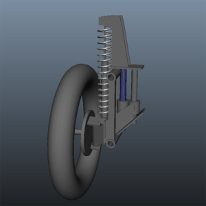
Sliding Pillar
traditional
5 inches of travel
Moves in line with lean angle
Max lean angle 40 degrees
Expensive and complicated fabrication
Shock must extend way above wheel
No bounce scrub
cantilevered
5 inches of travel
Moves in line with lean angle
Suspension does not extend above wheel height
Max lean angle 40 degrees
Expensive and complicated fabrication
No bounce scrub
Side linkage unsightly
Side linkage will require wider track
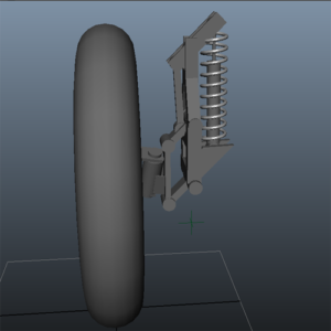
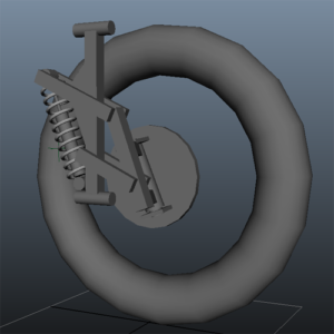
Leading Arm
5 inches of travel
Moves in line with lean angle
Suspension does not extend above wheel height
Max lean angle 40 degrees
Slightly complicated fabrication
No bounce scrub
Significant bounce steer
Can be configured for anti-dive when breaking.
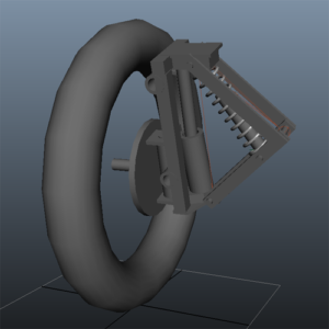
Rotating Leading Arm
5 inches of travel
Moves in line with lean angle
Suspension does not extend above wheel height
Max lean angle 40 degrees
Complicated fabrication
No bounce scrub
No bounce steer
Can be configured for anti-dive when breaking.
In summary, I conclude that the Rotating Leading Arm suspension is the best choice for suspension design for the following reasons:
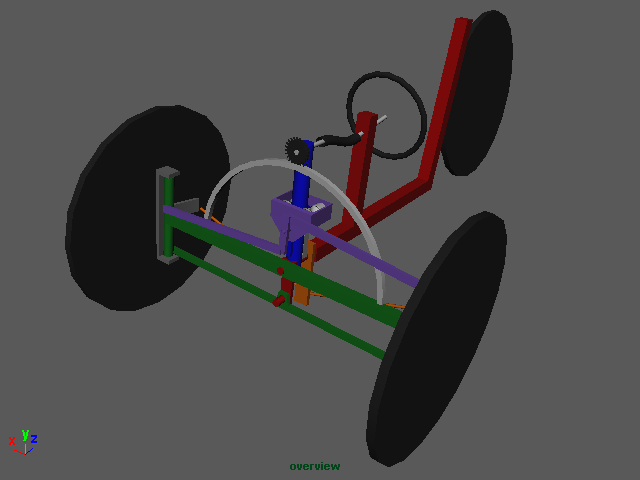
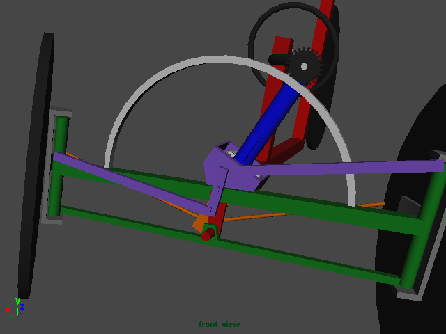
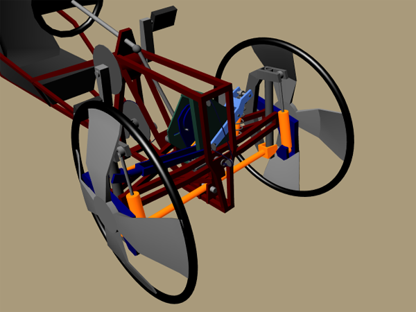
This illustrates a simplified all mechanical version of my free to caster reverse-trike. It has the ability to transition between free to caster and normal steer modes. I tried to make the mechanics as simple as possible and hopefully not require power assist to lean a human powered bike with rider.
To describe how it works I’ll start off with the four bar parallelogram shown in green. The wheel spindles rotate around the uprights. The leaning body of the bike (shown in red), rotates on an axis at the center of the top horizontal bar. The leaning body also has an arm that connects to the lower bar that keeps the bike parallel with the uprights on the sides of the four bar parallelogram. Added to the top horizontal bar is a vertical bar (shown in blue) that I call the” actuator bar”. It rotates at its base on the same axis as the leaning body at the center of the top horizontal bar. On the top of the actuator bar there is a pinion gear that connects to the steering wheel with a flexible cable (like used on a Ford Pinto steering shaft). When the steering wheel is turned the pinion gear engages a curved rack that has its radius around the pivot point of the actuator bar. It is the actuator bar that drives both lean and steer.
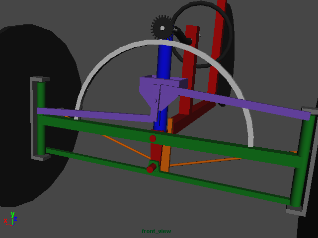
On the front side of the actuator is a Watt’s linkage (shown in purple) that connects the uprights of the four bar parallelogram to the actuator bar via a connector that can roll up and down on the actuator bar, I call this rolling connector the” transition device”.
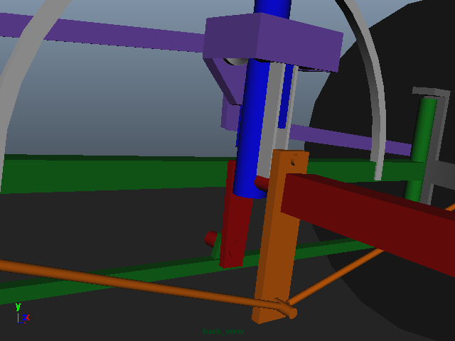
On the backside of the actuator bar there is a pair of leaf springs that are bolted at the top of the Springs to the actuator bar. The bottom of the two springs clamp a Pitman arm (shown in orange) that rotates freely around the same axis as the actuator bar. Steering rods connect the Pitman arm to the wheel spindles. In free to caster mode the Springs only lightly push the Pitman arm in the direction of steer, allowing the wheels through centrifugal force to caster to the proper angle of steer for the current speed and lean angle of the bike. Adding a damper to the Pitman arm may assist in the natural counter steer of free to caster.
To transition from free to caster to normal steer the transition device moves down the actuator from its top position to the bottom. This causes two things to happen simultaneously. The Springs that connect the Pitman arm, progressively clamp the Pitman arm to the movement of the actuator bar by the rollers in the transition device as it lowers, and the pivot point of the Watt’s linkage goes to or close to the pivot point of the actuator bar. This results with the steering being firmly locked to the rotations of the steering wheel, and little or no lien of the bike, because there is less lateral movement of the Watt’s linkage the closer it is to the axis of the actuator bar.
Having the pinion gear at the top of the blue bar gives the most leverage to allow for (hopefully) no power steering requirements. In addition I plan to add springs that pull the parallelogram square, this should cause a self righting effect and hopefully balance out effort between leaning into and away from gravity. For the bicycle, the transition between normal steer and free to caster will be manual because the bike is really intended as a proof of theory for the motorcycle I plan to build, but it could use a hand lever with cables and pulleys to raise and lower the transition device.
The motorcycle version will use a small winch motor or hydraulics to raise and lower the transition device. Power steering will also be used to assist leaning effort.
Ok, the above execution of my concept has been modified. I have a much simpler version now. Unfortunately I have so little time to work on it, that I have not had time to make any drawings, as I would rather spend the 6 hours a month I get to work on it in the garage. The new system uses a chebyshev linkage between the control arm and the upright of the 4 bar instead of a Watt’s linkage. Instead of the flex-drive it uses a telescoping shaft with universal joints and instead of the curved rack it uses a chain and sprockets to rotate the actuator arm around a sprocket hard fastened to the non tilting bottom bar of the 4 bar. Two leaf springs mounted on the control arm clamp a Pitman Arm connected to the steering of the wheels. The springs allow the wheels to free caster, but also put pressure on them to turn in the desired direction. As the chebyshev linkage connected to the control arm moves from the top of the control arm to the bottom, two things happen. The angle of the uprights compared to the control arm reduces pulling them from any lean to an upright position. At the same time rollers on the leaf springs clamp them tighter to the Pitman arm until the Pitman arm is forced to move 100% with the control arm. The end result is a self righting transition from tilting free to caster to non-tilting normal steer, and of course back again. The transition would take place between the speeds of 5 to 10 mph.
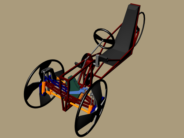
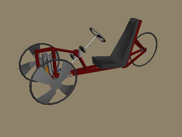
The above image is a link to a video that illustrates my refined concept for a human powered tilting reverse trike (two wheels in front one in back), that can transition between steering by leaning and non leaning normal steer like a car for slow speeds. Steering by leaning works by tilting the wheels and body of the bike while the front wheels are free to caster (FTC) to the proper steering angle for the angle of lean and speed using gyroscopic effect.
Steering is done via a steering wheel that connects to the lean/steer mechanism (shown in green) through a shaft with universal joints that allow it to move with the leaning body and connect to the steering/lean mechanism through gears mounted on the non-tilting sub frame. The sub-frame maintains parallel to the ground and the front wheels and leaning body are attached to it.
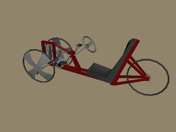
Basic operation would be while stopped, the vehicle is locked in non-lean normal steer mode. A hand lever unlocks the lean mechanism and engages the pedals of the bike to the lean mechanism through a clutch, cables, and guide wheels. Pedaling forward propels the vehicle forward while transitioning you to the free to caster mode by winching a connecting bar (dark blue) from from a point close to the lean mechanism’s axis to the it’s top, thus changing the ratio of lien to steer input. At the same time the connecting bar is being raised a cam is gradually loosening spring tension on a Pittman arm unlocking steering from the movement of the steering wheel, allowing the wheels to free Caster. The Pittman arm also acts as a tie rod with an Ackerman affect. When in free to caster mode engaging the transition clutch and pedaling backwards transitions to normal steer while pedaling has no effect on the motion of the bicycle.
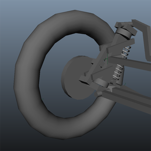
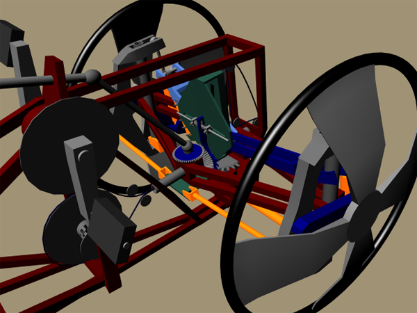
The use of the steering wheel will require that breaking must be done by pushing the steering wheel forward using a balancing disk to disperse the pressure evenly through cables to breaks on all three wheels. This concept shows leading arm front suspension on the front wheels that will most likely not be included due to to weight considerations, and will have to wait for the motorcycle powered version.
It also shows a dampened spring assist for the transition to normal steer. On a motorcycle this would be hydraulic and would power the transition between normal steer and Free to Caster.
Because of my lack of experience in fabrication, hydraulics and limited funds I thought it would be a smart move to start with a smaller project then a motorcycle engine leaning reverse trike. Also because human powered doesn’t require registration by the motor vehicle department I’ll be able to test this in my neighborhood. So by building this first I’ll get to practice my fabrication skills on something that probably won’t go much over 15 miles an hour, so if my welds break I won’t break my neck. The other important aspect of building this is to learn more about how the three different modes of steering and leaning work and feel to the driver in a reclined position using a steering wheel.
The basic design will consist of hacking apart a cruiser bike with a coaster brake, making two front wheels out of aluminum honeycomb and salvage bike rims. I plan on using go kart hubs, steering wheel and shaft, and will either use a small rack and pinion or geared lever coming off of the steering shaft to drive two closed circuit hydraulics systems. One system is for steering the other for leaning. Hydraulic valves will control the flow to allow me to operate the trike in three different modes, normal steering, counter steering, and free to caster. I may eventually also use this human powered reverse trike as a testbed for the sensors and electronics for controlling the hydraulic valves automatically. This will require the addition of a heavy 12 V battery so I might also add an electronic assist to the drivetrain.
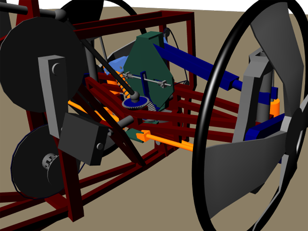
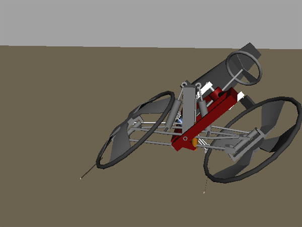
This is an animated crude 3-D model of my human powered leaning reverse trike. It will be a test bed for the final product which will be a motorcycle engine powered leaning reverse trike. This trike will use a system of hydraulic valves and actuators to allow three different modes of steering. Actuators acting as pumps in duel closed hydraulics circuit are driven by a rack and pinion connected to the steering wheel.
The three modes are:
Normal Steering – The trike does not lean. Turning the steering wheel to the left turns the wheels to the left, like driving a car.
Counter Steering – The wheels are turned in the opposite direction of the steering wheel forcing the trike to lean and turn in the direction the wheel was turned, just like a motorcycle.
Free to Caster – Turning the steering wheel leans the trike in that direction at the same time some counter steer is applied to the wheels to assist in the leaning effort, but wheels are free to caster to the proper angle of turn based on the angle of lean.
The final motor powered version will use sensors and a computer controller to switch between modes for optimum performance and rider comfort. Power assist will be added to the steering shaft for the heavier vehicle.