Author Archives: Dave

Front suspension design for a Free To Caster tilting reverse trike

I have explored 3 basic suspension types for my tilting Free To Caster reverse trike. I will explain what I feel are the pros and cons of each with some illustrations of various concepts.

Scrub is when the contact patch moves sideways relative to the plane of the wheel. Scrub does not happen when the suspension travels inline with the lean angle.

Track is the distance between between left and right contact patch of the wheels. When suspension travel moves inline with the lean angle, at high lean angles track can be reduced. This has less negative effect than scrub.

  • Double A-arm
    • Short A-arm

      • 4 inches travel (may be able to get 5 inches if max lean is reduced to 40 degrees)
      • 1 inch bounce scrub
      • Extra linkage makes it slightly more complicated than long a-arm
      • Max lean angle 45 degrees
      • Taller than wheel height


    • Long A arm

      • Clean look
      • Could be cantilevered to have shock inboard
      • Max lean angle 45 degrees
      • 9 inches of travel possible
      • Minimal bounce scrub
      • Simple construction
      • Does not move in line with lean angle which may cause bounce force to effect lean angle


  • Sliding Pillar
    • traditional

      • 5 inches of travel
      • Moves in line with lean angle
      • Max lean angle 40 degrees
      • Expensive and complicated fabrication
      • Shock must extend way above wheel
      • No bounce scrub


    • cantilevered

      • 5 inches of travel
      • Moves in line with lean angle
      • Suspension does not extend above wheel height
      • Max lean angle 40 degrees
      • Expensive and complicated fabrication
      • No bounce scrub
      • Side linkage unsightly
      • Side linkage will require wider track


  • Leading Arm

    • 5 inches of travel
    • Moves in line with lean angle
    • Suspension does not extend above wheel height
    • Max lean angle 40 degrees
    • Slightly complicated fabrication
    • No bounce scrub
    • Significant bounce steer
    • Can be configured for anti-dive when breaking.


  • Rotating Leading Arm

    • 5 inches of travel
    • Moves in line with lean angle
    • Suspension does not extend above wheel height
    • Max lean angle 40 degrees
    • Complicated fabrication
    • No bounce scrub
    • No bounce steer
    • Can be configured for anti-dive when breaking.


In summary, I conclude that the Rotating Leading Arm suspension is the best choice for suspension design for the following reasons:

  1. 5 inches of travel
  2. Moves with lean angle.
  3. Suspension does not extend above wheel height.
  4. No bounce steer.
  5. No bounce scrub.
  6. Can be configured for anti-dive when breaking.

Simplified Concept for Tilting Trike

This illustrates a simplified all mechanical version of my free to caster reverse-trike. It has the ability to transition between free to caster and normal steer modes. I tried to make the mechanics as simple as possible and hopefully not require power assist to lean a human powered bike with rider.

Simple transition tilting trike

To describe how it works I’ll start off with the four bar parallelogram shown in green. The wheel spindles rotate around the uprights. The leaning body of the bike (shown in red), rotates on an axis at the center of the top horizontal bar. The leaning body also has an arm that connects to the lower bar that keeps the bike parallel with the uprights on the sides of the four bar parallelogram. Added to the top horizontal bar is a vertical bar (shown in blue) that I call the” actuator bar”. It rotates at its base on the same axis as the leaning body at the center of the top horizontal bar. On the top of the actuator bar there is a pinion gear that connects to the steering wheel with a flexible cable (like used on a Ford Pinto steering shaft). When the steering wheel is turned the pinion gear engages a curved rack that has its radius around the pivot point of the actuator bar. It is the actuator bar that drives both lean and steer.

Simple transition tilting trike front view

On the front side of the actuator is a Watt’s linkage (shown in purple) that connects the uprights of the four bar parallelogram to the actuator bar via a connector that can roll up and down on the actuator bar, I call this rolling connector the” transition device”.

Simple transition tilting trike back view

On the backside of the actuator bar there is a pair of leaf springs that are bolted at the top of the Springs to the actuator bar. The bottom of the two springs clamp a Pitman arm (shown in orange) that rotates freely around the same axis as the actuator bar. Steering rods connect the Pitman arm to the wheel spindles. In free to caster mode the Springs only lightly push the Pitman arm in the direction of steer, allowing the wheels through centrifugal force to caster to the proper angle of steer for the current speed and lean angle of the bike. Adding a damper to the Pitman arm may assist in the natural counter steer of free to caster.

Simple transition tilting trike normal steer mode

To transition from free to caster to normal steer the transition device moves down the actuator from its top position to the bottom. This causes two things to happen simultaneously. The Springs that connect the Pitman arm, progressively clamp the Pitman arm to the movement of the actuator bar by the rollers in the transition device as it lowers, and the pivot point of the Watt’s linkage goes to or close to the pivot point of the actuator bar. This results with the steering being firmly locked to the rotations of the steering wheel, and little or no lien of the bike, because there is less lateral movement of the Watt’s linkage the closer it is to the axis of the actuator bar.

Having the pinion gear at the top of the blue bar gives the most leverage to allow for (hopefully) no power steering requirements. In addition I plan to add springs that pull the parallelogram square, this should cause a self righting effect and hopefully balance out effort between leaning into and away from gravity. For the bicycle, the transition between normal steer and free to caster will be manual because the bike is really intended as a proof of theory for the motorcycle I plan to build, but it could use a hand lever with cables and pulleys to raise and lower the transition device.

The motorcycle version will use a small winch motor or hydraulics to raise and lower the transition device. Power steering will also be used to assist leaning effort.

Ok, the above execution of my concept has been modified. I have a much simpler version now. Unfortunately I have so little time to work on it, that I have not had time to make any drawings, as I would rather spend the 6 hours a month I get to work on it in the garage. The new system uses a chebyshev linkage between the control arm and the upright of the 4 bar instead of a Watt’s linkage. Instead of the flex-drive it uses a telescoping shaft with universal joints and instead of the curved rack it uses a chain and sprockets to rotate the actuator arm around a sprocket hard fastened to the non tilting bottom bar of the 4 bar. Two leaf springs mounted on the control arm clamp a Pitman Arm connected to the steering of the wheels. The springs allow the wheels to free caster, but also put pressure on them to turn in the desired direction. As the chebyshev linkage connected to the control arm moves from the top of the control arm to the bottom, two things happen. The angle of the uprights compared to the control arm reduces pulling them from any lean to an upright position. At the same time rollers on the leaf springs clamp them tighter to the Pitman arm until the Pitman arm is forced to move 100% with the control arm. The end result is a self righting transition from tilting free to caster to non-tilting normal steer, and of course back again. The transition would take place between the speeds of 5 to 10 mph.

Concept for human powered leaning trike

Refined concept of human powered leaning reverse trike
The above image is a link to a video that illustrates my refined concept for a human powered tilting reverse trike (two wheels in front one in back), that can transition between steering by leaning and non leaning normal steer like a car for slow speeds. Steering by leaning works by tilting the wheels and body of the bike while the front wheels are free to caster (FTC) to the proper steering angle for the angle of lean and speed using gyroscopic effect.

Steering is done via a steering wheel that connects to the lean/steer mechanism (shown in green) through a shaft with universal joints that allow it to move with the leaning body and connect to the steering/lean mechanism through gears mounted on the non-tilting sub frame. The sub-frame maintains parallel to the ground and the front wheels and leaning body are attached to it.

Normal steer mode
Basic operation would be while stopped, the vehicle is locked in non-lean normal steer mode. A hand lever unlocks the lean mechanism and engages the pedals of the bike to the lean mechanism through a clutch, cables, and guide wheels. Pedaling forward propels the vehicle forward while transitioning you to the free to caster mode by winching a connecting bar (dark blue) from from a point close to the lean mechanism’s axis to the it’s top, thus changing the ratio of lien to steer input. At the same time the connecting bar is being raised a cam is gradually loosening spring tension on a Pittman arm unlocking steering from the movement of the steering wheel, allowing the wheels to free Caster. The Pittman arm also acts as a tie rod with an Ackerman affect. When in free to caster mode engaging the transition clutch and pedaling backwards transitions to normal steer while pedaling has no effect on the motion of the bicycle.

Free to caster mode
The use of the steering wheel will require that breaking must be done by pushing the steering wheel forward using a balancing disk to disperse the pressure evenly through cables to breaks on all three wheels. This concept shows leading arm front suspension on the front wheels that will most likely not be included due to to weight considerations, and will have to wait for the motorcycle powered version.

transition spring assist
It also shows a dampened spring assist for the transition to normal steer. On a motorcycle this would be hydraulic and would power the transition between normal steer and Free to Caster.

Preliminary leaning reverse trike concept

First prototype design of leaning reverse trike

Because of my lack of experience in fabrication, hydraulics and limited funds I thought it would be a smart move to start with a smaller project then a motorcycle engine leaning reverse trike. Also because human powered doesn’t require registration by the motor vehicle department I’ll be able to test this in my neighborhood. So by building this first I’ll get to practice my fabrication skills on something that probably won’t go much over 15 miles an hour, so if my welds break I won’t break my neck. The other important aspect of building this is to learn more about how the three different modes of steering and leaning work and feel to the driver in a reclined position using a steering wheel.

The basic design will consist of hacking apart a cruiser bike with a coaster brake, making two front wheels out of aluminum honeycomb and salvage bike rims. I plan on using go kart hubs, steering wheel and shaft, and will either use a small rack and pinion or geared lever coming off of the steering shaft to drive two closed circuit hydraulics systems. One system is for steering the other for leaning. Hydraulic valves will control the flow to allow me to operate the trike in three different modes, normal steering, counter steering, and free to caster. I may eventually also use this human powered reverse trike as a testbed for the sensors and electronics for controlling the hydraulic valves automatically. This will require the addition of a heavy 12 V battery so I might also add an electronic assist to the drivetrain.

This is an animated crude 3-D model of my human powered leaning reverse trike. It will be a test bed for the final product which will be a motorcycle engine powered leaning reverse trike. This trike will use a system of hydraulic valves and actuators to allow three different modes of steering. Actuators acting as pumps in duel closed hydraulics circuit are driven by a rack and pinion connected to the steering wheel.

First prototype design of leaning reverse trike

The three modes are:

Normal Steering – The trike does not lean. Turning the steering wheel to the left turns the wheels to the left, like driving a car.

Counter Steering – The wheels are turned in the opposite direction of the steering wheel forcing the trike to lean and turn in the direction the wheel was turned, just like a motorcycle.

Free to Caster – Turning the steering wheel leans the trike in that direction at the same time some counter steer is applied to the wheels to assist in the leaning effort, but wheels are free to caster to the proper angle of turn based on the angle of lean.

The final motor powered version will use sensors and a computer controller to switch between modes for optimum performance and rider comfort. Power assist will be added to the steering shaft for the heavier vehicle.

A pdf file with a description of my leaning reverse trike hydraulic circuits is available here.

First prototype design of leaning reverse trike

Selecting A Doner Motorcycle

Which comes first, choosing a motorcycle to to design your leaning reverse trike around or designing your leaning reverse trike and then find the doner motorcycle that best suites your design? Its a classic chicken or the egg scenario. Unless you already have a motorcycle ready for the operating table, the best answer is to do a little of both. You should at least be settled in your mind about engine placement (fore, mid, or aft), drivetrain (chain or shaft), and how you will implement a reverse gear. Are you building a cruiser or a race car? What is your budget for the motorcycle? These all should have an impact on your motorcycle selection. Once you have figured out the ideal motorcycle for your you leaning reverse trike, it’s time to obtain it and design the details of your leaning reverse trike around it.

My First Choices

Currently I am leaning toward a cruiser with a front mounted engine, drive shaft and a stock reverse gear. I also want reliability and parts availability. This leaves me with three motorcycle model choices:

Honda GL1800

The Honda GL1800 has all the requirements I have for my concept of the leaning reverse trike, but is probably out of my price range. A 2002 GL1800 with 100,000 miles and some major front end damage will go for over $4000.00 at a salvage auction.

Honda GL1500

The Honda GL1500 also has all the requirements I have for my concept of the leaning reverse trike and the price is more reasonable. On the down side it is an older motorcycle no longer produced and tends to have higher mileage and more ware and tare. If I can find one in the last few years of its production run at the right price I will get it.

BMW K1200LT

The BMW K1200LT is an excellent choice, it too meets all my leaning trike concept requirements. The BMW K1200LT is harder to come by, but go for a more reasonable price at salvage auction than the GL1800. I also am vainly thrilled with the simple idea of having a BWM hood emblem on the finished reverse trike.

Other Doner Motorcycle Options

If I just remove the stock reverse gear from my requirements, the list of motorcycles to choose from grows much larger. It now includes most shaft drive motorcycles. Because I want a front mounted engine I will be needing to extend the drive shaft from the engine in the front to the rear swingarm. I can use a aftermarket reverse gearbox inline with the driveshaft. The gearbox will cost an additional $1000.00 – $1600.00. This would give me a very robust reverse gear, but need to do more research to decide if it is cost effective.

If I were to use a rear engine mount, I would no longer want a shaft drive and I could use an after market reverse gear box as a jack shaft on a chain or belt drive. There are also reverse gear kits for Harley Davidson motorcycles. I could use almost any chain driven motorcycle on the market.

Screw It! I’m getting a Suzuki Hayabusa (GSX1300R). Stick a reverse gear and jackshaft on it and I’ll be carving those canyons! Just kidding, well maybe not?

Reversing a Reverse Trike Motorcycle

Most motorcycles don’t have a reverse gear, unless you consider the Fred Flintstone reverse of putting your feet down and pushing. In an enclosed trike, that is not possible. How you resolve this is something I would prefer to decide early on before getting the doner bike. You basically have three choices: Use a motorcycle with a stock reverse gear, buy an after market reverse gear, or design and build your own.

Motorcycle with a stock reverse gear

There are very few motorcycles that come with a reverse gear. In fact I currently only know of three major manufacturer motorcycles with a reverse gear, the Honda GL series starting with the older discontinued GL1500 and the current GL1800 and the BMW K1200LT. These are shaft drive and use the electric starter motor to power a reverse gear in the transmission that must be engaged first. The Can Am Spider a stock non-leaning reverse trike has a stock reverse gear with a belt drive. A fourth motorcycle manufacturer is the Russian Irbit Motorcycle Works (IMZ) who produces the Ural which is a heavy sidecar motorcycle equipped with a four-stroke, air-cooled, flat-twin engine, a four speed gear box with reverse gear and shaft drive.

After market reverse gear for trike motorcycles

Below are links to several after market reverse gears for motorcycles, trikes, or motorcycle powered cars.

Non Gearbox Reverse Options

On the internet I have found ingenious solutions to getting motorcycle powered cars and trikes a reverse gear using automotive starter motors engaging a gear connected to the drive shaft or drive chain. This will require a stout 12 volt electrical system and usage could quickly drain your battery. But you have this same problem the the Honda and BMW motorcycles stock reverse gears as well

Hydrostatic Transmission

Another idea less explored would be to use a Hydrostatic Transmission. Using a bike engine with a dry clutch like a BMW or Moto Guzzi you could replace the gearbox with a variable ratio hydraulic pump and on the driveshaft at the swingarm base put a hydraulic motor. This would also work for a belt or chain rear drive by putting a pulley or sprocket on the hydraulic motor. This would have a lot of advantages like allowing more freedom in engine placement with out worry of how to get the power to the rear wheel. A Hydrostatic Transmission gives you a smooth transition from stopped to full speed without coming off the power-band, by just pushing a lever forward to go forward and faster or pulling the leaver back to slow or reverse. There is a slight loss of efficiency with hydraulics over a direct drive 80% vs. 95%, but it may well be worth it. KTM and Yamaha have experimented with 2 wheel drive motorcycles by mounting a Hydraulic pump at the drive sprocket and running flexible hydraulic lines to a Hydraulic motor on the front forks with a gear driving the front wheel. The motors are surprisingly small and powerful. For a non leaning reverse trike this would be a good solution for front wheel drive by putting hydraulic motors on each wheel

Making a Leaning Reverse Trike lean and turn

How do you make an enclosed leaning reverse trike lean?

That my friends is the million dollar question that I need to find the answer to.

Only a few people have built a leaning reverse trike and used a multitude of technologies to control steering and leaning, some with better results than others. Below I list a few of these technologies with their major pros and cons. In future posts I’ll get into more detail on what I consider to be the better technologies for leaning and steering a leaning reverse trike in greater detail. But first I should give a little technical discussion on the mechanics of how a motorcycle leans and turns.

The following equation can be used to determine the optimum angle of lean based on the current speed of the leaning reverse trike and radius of the turn it is making. The radius of a turn can be determined by the angle the wheels are turned and the length of the wheelbase. That is in a perfect world where wheels maintain traction with the road at all times. This will not work if you are corrective steering for a rear end slide out, in fact using this equation to set a lean angle with servos or direct linkage, would pitch the leaning reverse trike into a high side leaning the motorcycle to the outside of the turn.

radius of turn = *wheelbase / sine( turning angle of wheel )
gravity constant = 386.088 (in inches per second)
speed = (*wheel diameter x 3.14159) x revolutions per second
Angle of lean = tangent( (speed x speed) / (radius of turn x gravity constant) )

* measurements in inches

How a motorcycle leans and turns using gyroscopic effect

I am not going to get into the mathematics of gyroscopic effects. For one it’s over my head and if I ever do tackle that job it will need its own post. So, what I will try to do is give the basics of gyroscopic effects in plain English as to how it pertains to all single-track vehicles, like a bike or motorcycle. All moving objects have inertia, meaning they want to continue the existing motion in a straight line. A wheel spinning around a center axis is doing just that, but because the motion of the wheel is constrained by the central axis the wheel continues to rotate. If a force is applied to the wheel to change the rotation of the wheel on any one of its two other axis, the inertia will cause a reaction on the other remaining axis to try and maintain its original path of motion. If you steer the wheel to the left it will cause the wheel to lean to the right. If you lean the wheel to the left it will steer to the the left. To make a left hand turn on a motorcycle, you first counter steer to the right by pushing the left handlebar forward. This does two things. It steers your front wheel to the right causing the gyroscopic effect to lean the motorcycle to the left. Now that the motorcycle is leaning to the left the gyroscopic effect causes the front wheel to turn (caster) to the left to the correct angle of turn for the amount the motorcycle is leaning and its speed.

If you are building a leaning reverse trike where the wheels don’t lean (a multi-track vehicle), you will not need to recon with these forces, but you will need some way to lean your vehicle that can fight the centrifugal forces as you make a turn.

If you want a reverse trike where the wheels lean, you are building what is called a virtual single-track vehicle. This type of vehicle does have to deal with the powerful gyroscopic forces. You can get them to work for you like on a motorcycle, or you will have to fight them. A true virtual single-track vehicle would handle just like a motorcycle and use counter steering to control turning and lean. You will need the same skill level to drive it as a motorcycle and if it is enclosed you will need a way to lock the tilt for low speeds and while stopped. The other option for a leaning reverse trike is a Free To Caster (FTC) vehicle. A Free to Caster trike skips the counter steering and uses power assisted controls to lean the trike and its wheels. There is no steering linkage to the wheels, they are allowed to find through gyroscopic effect to find the proper angle of turn for the amount they are leaned. Because the rider always has control over the amount of lean there is a much less chance of low-siding or high-siding a leaning reverse trike.

Purely mechanical straight linkage

A purely mechanical straight linkage is where the angle of the steering wheel is directly linked to the leaning of the trike, so that when you steer, the amount of lean is directly related to the angle of the front wheels, or in some instances the steering is directly related to the angle of lien. This is the simplest to implement and as long as your speeds are very low (less than 20 mph) it will work. The problem is, that the angle of the lien is in direct proportion to the speed and the radius of the curve it is traveling in. In other words the faster you go around a curve the more the bike has to lean. A purely mechanical straight linkage does not take this into account and you’ll most likely be leaning too much for a slow turn or not enough for a fast one. One way around this would be to use a constant variable transmission or Reeves Drive to adjust the ratio between steering and leaning based on the speed of the leaning reverse trike. This would require a speed sensor and computer controlled servo to set the ratio of the reeves drive. As mentioned above if you are corrective steering for a rear end slide out, a mechanical linkage between steering and leaning would lean the trike to the outside of the turn, increasing the possibility of a rollover.

Using electronic sensors, computers and servo motors

Instead of using a continuous variable transmission as above you could use sensors to determine speed and steering wheel degree of turn to calculate the proper angle of lean and use a servo to lean the motorcycle. This setup still has the problem of the computer thinking you are making a right turn when you are correcting for a rear end slide-out while turning left and causing the reverse trike to lean to the outside of the turn increasing the possibility of a rollover. Using Gyros and accelerometers to calculate lean angle based on longitudinal and lateral acceleration (how fast the vehicle is traveling sideways) seems to me to be a better solution, but it does have its draw backs too. An accelerometer can read the lateral force (how many Gs are pulling on the trike sideways) exerted on the reverse trike as it goes around a corner, and based on that force a small computer can control a servo to lean the trike to the proper angle. This solves the problem of corrective steering in a slide causing a lean in the wrong direction. The problem with this is that the lean of the leaning reverse trike will always lag slightly behind the turn of the wheels and as the physics of gyroscopic motion mentioned above turning a wheel will cause it to want to lean to the outside of the turn, so the servo controlling the lean of the reverse trike will have to fight the gyroscopic effect of the wheels and the lateral forces on the trike. This adds up to requiring a heavy duty servo and the electrical and or hydraulic system to power it. I also wonder about the ride sensation and stability caused by this delay in lean. If using wheel rotation to calculate speed an ABS brake system must be used so panic stop with the wheels locked up will not be read as standing still. Adding a longitudinal accelerometer reading to the wheel rotation would be a good idea to test against false speed readings.

Free to Caster

Look Ma no hands! Would be a good subtitle for this method of steering a leaning reverse trike. Free to Caster steers by leaning the wheels and trike and allowing the gyroscopic effect to turn the wheels. There is no steering linkage. This resolves most of the issues mentioned above with corrective steering in a slide and it has physics working for you instead of fighting you. Besides the unsettling idea of not having direct control over where your wheels are pointing there is one big problem with a free to caster leaning reverse trike. Gyroscopic effect diminishes and stops all together at slow speeds. Without gyroscopic effect you will not be able to steer; so, a hybrid system of direct linkage will need to be used to control the vehicle at slow speeds or while reversing that can transition smoothly to Free to Caster once gyroscopic effect speeds have been reached. This transition should be invisible to the operator and needs to be able to happen even in a turn while accelerating or breaking. One of my big questions about Free to Caster is — What happens in a panic stop when the wheels are locked up by breaks? Panic situations are when you need the most control. If in a locked wheel panic stop the transition from Free to Caster to direct steering linkage will have to be automatic, fast, and not confuse the operator or put him in peril by a sudden change in the way the leaning reverse trike maneuvers or handles.

After talking with Tom Blackburn, who is one of the few to actually build a free to caster leaning reverse trike. I have apparently been over thinking the transition to and from free caster, according to Tom even at very low speeds he is in free caster mode. Only when stopped or reversing is the steering angle of the wheels hydraulically locked to the lean of the motorcycle. Otherwise opening an adjustable needle valve allows the wheels to find its own steering angle based on the lean, while being nudged in the right direction by the hydraulics. He also said that in a panic stop when all wheels are locked up the trike will continue to go straight because of the downward pressure on the front wheel trail. I am coming to the happy conclusion that this is the way to go.

The one negative I have to Tom’s set up is that the lean of the trike is directly linked to the steering wheel, so that the trike leans even when stopped or reversing, which sounds like it would feel very awkward feeling while parallel parking. I would like to have a system where the lean is hydraulically connected to the steering wheel, so that when not in free caster mode and the steering wheel is turned the motorcycle can only be leaned in a direction toward vertical, while the wheels steering angle are locked hydraulically to the steering wheel rotation.

Free To Caster (FTC) transition to Non Lean Normal Steer (NLNS)

Drawing of Free to caster to normal steer transition mechanism
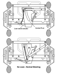
Click image for a larger one.

The following is a concept. It has not been tested and is only put forth as a suggestion to try.

Problem: how to transition a reverse trike from FTC to NLNS simply, smoothly, safely, and without making the driver feel the difference.

The following equation can determine the proper lean angle and steering angle for a single track vehicle based on the wheelbase length, speed, and radius of the curve being driven.

Angle of lean = tangent( (speed x speed) / (radius of turn x gravity constant) )

Below are some example values done to make the sharpest turn at the given speed with a maximum steering angle of 30 degrees and maximum lean angle of 45 degrees with a 90 inch wheelbase.

MPH Lean Steering Lean:Steer – Ratios
0 0 30 0.000:1.000
2.5 .02 30 0.006:1.000
5 6.65 30 0.148:1.000
7.5 14.69 30 0.326:1.000
10 36.06 30 0.555:1.000
12.5 45 30 0.801:1.000
14.6 45 30 1.000:1.000
17.5 45 21.02 1.000:0.700
20 45 16.09 1.000:0.536
40 45 4.023 1.000:0.143
80 45 1.006 1.000:0.033

Considering the above chart at 14.6 miles per hour, steering and lean, are at a 1 to 1 ratio. This seems like the time to start or end the transition with the other start end point at 0. From that speed and up the trike is full FTC. My original idea was to at this speed, lock the steering directly to the steering wheel with a clutch and as speed decreases reduce the amount of lean to steering wheel rotation until at 0 MPH it will not lean at all, just as it does naturally as the numbers above show. The sudden clamping of the steering angle at a given moment with the clutch is obviously not a good idea and after some hints from Philip James, I now realize the steering must be allowed to adjust progressively less as the speed decreases from 14.6 mph. This can be done by putting a progressive spring in between the steering wheel and the steering rods, so that at FTC speed the spring is very soft offering little to no resistance letting the wheels be free to caster, at slow or stopped the spring is extremely stiff allowing no deviation from steering wheel input. FTC should be the failsafe mode. The transition should happen at a maximum speed to allow it to keep up with maximum acceleration from 0 to 15 mph. It don’t believe it would be harmful if the transition were a bit slower than a full panic stop this might even be preferred. This will require some form of powered actuator to perform the transition and a controller to set the actuator at the proper level at a given speed. Possible means of power are an electric servo controlled by speed sensors, hydraulic actuator powered by a pump driven by the drive chain whose power at 14.6 mph is just strong enough to make the transition to FTC, and possibly although I doubt it would have the strength, but a centrifugal governor driven by the drive chain that would be the actuator or at least control it.

The leaning ratio can be done progressively through the transition by moving one end of a rod in a slot on an arm rotated by the steering wheel that is connected to and pivots on a vertical bar of a four bar parallelogram. Moving the end of the bar in the slot closer or further away from the arms rotation axis changes the distance the bar can push or pull the four bar out of parallel, or how much the vehicle will lean. The actuator that controls the movement of this arm also controls what portion of a leaf spring can flex. The longer the flex length, the softer the spring. The spring is mounted on the same arm rotated by the steering wheel that controls the lean, and the spring connects to the steering rods. The leaf spring mounted on bar B connects to the steering rods. Bar B always has full range of rotation. It is the amount of flex allowed by rollers moved by bar C on the spring that makes the transition from the wheels being able to free caster to being locked to the rotation of bar B.

I have come to the conclusion that the leaf spring concept as described above is not the best solution. Instead as bar C is rotated down by bar E, a cam rotates causing a set of springs to progressively clamp the movement of the steering rods to the rotation of bar B. In Full FTC mode there would be no resistance for the wheels to free caster. With the leaf spring I believe there would be to much pressure to return the wheel to center. I have also updated the images to reflect a new placement of the actuator and the addition of bar E for rotating Bar C. The original drawing caused a triangulation which made leaning impossible.

To get feedback from the tilting beams and front wheels back to the driver, the steering wheel is directly connected to bar B through a double universal shaft that will stay with the leaning body and be attached to bar A. This means the driver is always connected directly to lean and/or steering. A standard hydraulic power steering setup gives the assist.

Engine Placement options for leaning reverse trike motorcycle

Engine placement is one of the first things that must be decided when designing your leaning reverse trike motorcycle. you basically have the option of front engine, mid-engined front, and mid-engined rear.

  • A front engine placement means that the motor is going to go before the front axle or over it.
  • A front mid-engine placement puts the motor just behind the front axle and before the passenger or rider.
  • A rear mid-engine placement places the motor behind the passenger but in front of the rear wheel.

All of these options have their advantages and disadvantages. An important thing to keep in mind is making sure there is space for all the other essentials that are required for leaning, steering, passengers and storage in your leaning reverse trike motorcycle.

The mid-engined rear mount is probably the simplest and most economical to implement for a leaning reverse trike motorcycle. You can basically take the front forks off of an existing motorcycle and attach the entire frame behind the passenger and just reroute throttle, break, shift and clutch controls. The downside is it makes the wheelbase very long, especially if you are building a two-seater. Because we are building a leaning trike you’ll want to keep weight centered, so having a second passenger sitting beside you means you’ll be unbalanced unless both passengers are the same weight and in the vehicle at all times together. It’s much better to build your leaning reverse trike motorcycle like a fighter jet, with passenger seated behind the driver.

The front engine placement is used by the RX3 a hybrid reverse trike. It uses a small diesel engine mounted before the front axle and uses a VW transmission with front wheel drive. This is an intriguing setup, with the advantage of having a very short distance from the motor to the wheels and keeping the bulk of the vehicle weight over the drive wheels. With this setup The motor and transmission would not tilt and would be mounted to the main frame. A sub-frame consisting of the driver cabinet and rear wheel would be the parts that lean. Because the engine will not lean, this causes several problems that would have to be dealt with. It would be best to not use a motorcycle engine. They are designed to lean and use centrifugal force to keep oil in place when the engine is at an angle through a turn. If the engine does not lean, all the oil will slosh to one side. Car engines are designed not to lean and are a better choice for this setup. Another problem is getting the controls from the leaning cab to the non leaning engine and transmission, and will require the use of hydraulics or cables. And the killer for this setup may be that the steering and leaning mechanisms may need to be located where the engine and/or transmission are located. Getting the engine to exhaust behind the riders may also get tricky.

The front mid-engine placement, locates the engine of your leaning reverse trike motorcycle between the front axle and the driver. This setup is best for shaft-drive motorcycle engines, but will require an extension of the drive shaft from the engine to the rear wheel. A chain drive is possible but will most likely require several jackshafts, or a jackshaft combined with an aftermarket reverse gearbox that can double as a jackshaft. It keeps the main weight of the vehicle close to the front wheels for better traction in cornering. You should be able to get a slightly shorter wheelbase with the Mid Engine Front than the Mid Engine Rear setup. The engine will lean with the bike getting more effect of weight transfer while leaning and keeps engine controls in line with the driver. While extending the drive shaft, an inline reverse gear box could be installed between the engine main shaft and the extension, allowing a wider range of engine choices for your leaning reverse trike motorcycle. I currently know of only two easily available production bikes with a drive-shaft and reverse gear as standard equipment. They are the Honda Goldwing (GL1500 and GL1800 Models) and the BMW k1200LT.

More on reverse gears